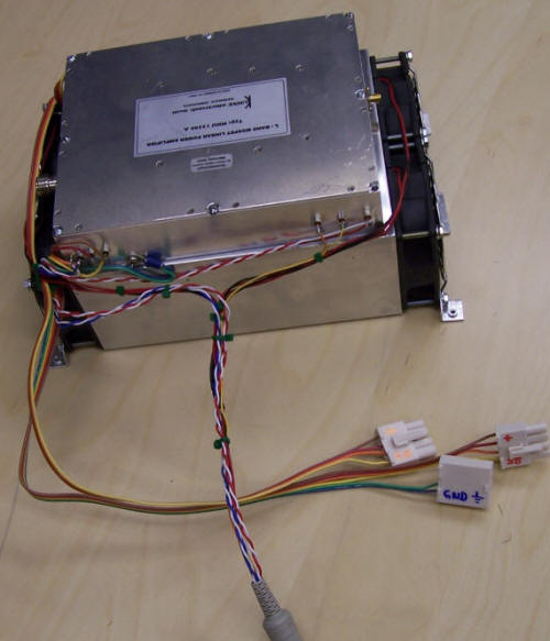
This module is an enormous improvement over the original amplifier, which could (episodically) deliver 200W and which required frequent module replacement. The higher operating voltage of the new module allows lower current wiring, which is more convenient and results in less voltage drop. It's also far more efficient.
Four fans seem to provide excellent cooling. I've added a temperature probe (not shown) at the air outlet to monitor operation. It remains largely cucumbric at the current <30% duty cycle. Because the amp is fully linear we will be able to run other modes such as SSB and JT65 in the future.
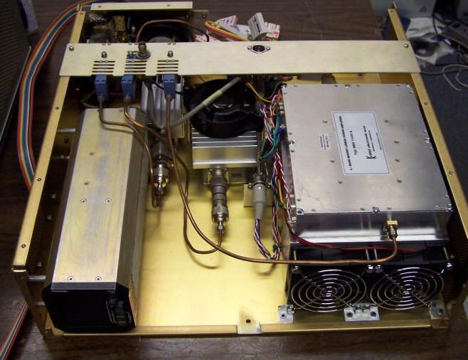
The Eventide Argus is being used as a CRT monitor for data display. (Sadly, no moving map is needed in the beacon at this time.)
This view is before the frequency reference and synthesizer have been installed in the open space between the amplifier and the Argus.
Not shown is the "head" for the R&S NAP power/reverse power meter, which is mounted on the rear panel directly behind the "sniffer."
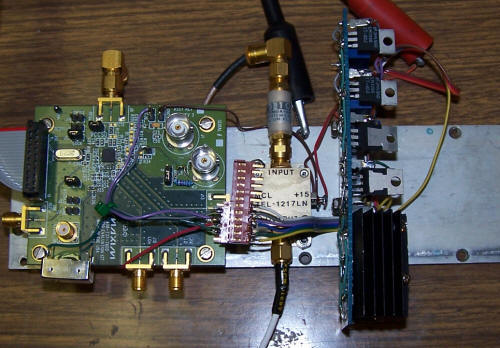
Because it was so settable, I decided to incorporate a normal ovenized 10MHz crystal as the frequency reference rather than use the external atomic standard. That way the exciter/amplifier is completely self-contained, and the frequency control "loop" is closed manually. Whenever I notice that the frequency error at 1296MHz starts to exceed 1 Hz, I just reset the synthesizer frequency. This tiny board replaces a 50lb+ HP synthesizer!
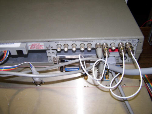
The left-hand module and connector has a number of relays that control amplifier power, select DC voltages to be measured, and perform other control functions.
After confirming all was OK, I whittled a front panel out of copperclad PC material and installed it in the final beacon rack.