|
 |
PriUPS Update 26 September 2005
|
 |
In my previous update I
offered a tentative solution to the inverter problem, that solution being to
use a computer UPS, which already has an inverter, and has batteries as well.
Advantages include not even needing the Prius for short outages, and
the ever popular "cheap." This update covers progress since I got the
inverter. Specifically:
When we began this saga, one of the first steps was removing
all the carstuff that protected the battery from my prying fingers.
That was done with the help of the step-by-step instructions in the
voluminous Prius manuals. The goal was to connect a power-take-off
from the HV battery, which I initially did with a simple
outlet strip.
However, the current rating for the outlet strip was only 15A, which is fine
for testing under benign conditions, but unsatisfactory for actual use.
Pete (who will reappear moments from now) happened to have a nice mating
pair of Anderson high power
connectors and offered them up for this project.
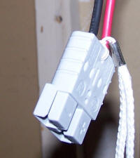 |
I had never actually seen connectors like this - they're pretty
nifty. The have spring loaded blades and mate with significant
pressure, but don't lock in a way that makes removal difficult. The attached cord is for demating - you yank on it and the pair comes apart without stressing
the wires themselves. For the Prius side of the connector, I
simply attached a couple of #8 wires with lugs on the end (and the
connector on the other end) to the battery terminals in the Prius.
Now I was all set to add a permanent connection, but
unfortunately... |
While I drove around in my now
high-noise Prius,
220V outlet strip dangling in the rear compartment, my alleged brain
methodically forgot where all those upholsteries and doohickii were supposed
to go. The very same Pete of recent connector fame said,
in effect, "Get out of the way." I was pleased to see that all the
parts (and all the screws) re-found their homes, and the car was back
together after his ministrations. With one addition:
 |
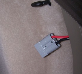
If you fold down the perfectly-normal-appearing rear seat (left)
you can access the full potential of the battery at the connector
that's otherwise wedged between the seat side and the side of the
car. This is all soft, insulating material and the connector
is very snug. |
 |
The next step was to get a cable from the garage to the
electrical distribution room, fortunately adjacent. I simply drilled a
hole in the wall between the two and ran a short piece of 3-conductor, 6AWG
flexible welding cable through it.
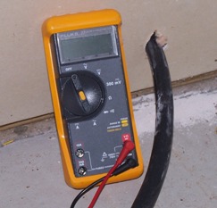 |
The black "hose" is actually a piece of welding cable brought
into the electrical distribution area. (DVM for size comparison
only.) On the right is the garage side of the cable, with a
connector attached. |
 |
Finally, I made an "extension cord" out of the same welding cable to connect
the Prius (using the blade connector behind the rear seat) to the cable going to
the electric room. Both the extension cord and the cable to the electrical
room are made from very heavy cable. It's overkill for the current
actually carried, but because the Prius delivers less voltage than the normal
rating of the UPS batteries, I was concerned about even the smallest voltage
drop. Using the cables I did I extrapolated less than 1.5V drop between
the car and the diode under peak load, and well under 1V drop under normal
operation with all the connectors in-line.
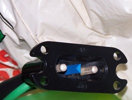 |
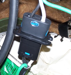
Here's a closeup of the heavy-duty connector I used for the
"extension cord." This is a "blind mating" connector. It's rated at 175 amps - I think it's normally used for
charging fork lifts. Although I mate and demate these connectors
manually, it should be possible to make matching fixtures on the wall
and the car so that one can simply drive into the garage and be
automatically connected.
This connector is also by Anderson. I made sure it was rated
for enough connect/disconnect cycles so that even with cycling it each
time the car is moved it should last as long as the car does. |
Having the three segments of cable detailed above gives extra flexibility.
The "extension cord" can be kept in the garage if that's the only place the car
will ever be plugged in, or carried in the car if the Prius will be used to provide
power elsewhere, since the fixed portion of the system can easily be recreated
at a vacation home, work, or wherever.
The nominal battery voltage of the UPS is 240VDC, and when fully charged it
is higher - typically between 250 and 260V. The Prius, as demonstrated in
my previous testing, typically cycles
between 210 and 235V. Because of the difference in voltages, one cannot
simply connect the two battery systems together. In addition to the
voltage problem, if the inverter battery were accidentally connected to the
Prius when the "ignition" was off, the car would be receiving high voltage out
of sequence, i.e., without the low voltage being turned on first. This
would probably damage it car and would discharge the UPS batteries as well.
The simplest strategy for solving this problem is to connect a diode between
the Prius battery and the inverter battery, and that's what I did. That
way, if the UPS battery voltage is higher than that of the Prius, the Prius
remains isolated. This is the normal case even during a short power
failure, as it takes a while for the UPS to discharge.
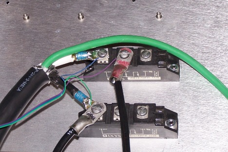 |
Shown at the left is a pair of heavy duty diodes. The bottom
one is being used only as a junction at the moment. The two black
wires going to the left terminal on the bottom diode are the DC negative
connection.
The white wire is the + output from the Prius, the black wire to its right
(with the red marker ink) is the + battery terminal of the UPS. When
the white wire is positive with respect to the black, the diode conducts
and power from the Prius goes to the UPS. The diodes are mounted on an
aluminum plate for heat dissipation. Even though the voltage drop
through the diode is less than a volt, it can get quite warm when
there's a lot of current flowing. |
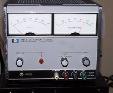 |
Recognize this?
This was the power supply I used to charge the test batteries.
It's now a pair of meters repurposed to measure the voltage of the Prius
(left) and UPS (right) batteries. Although the scales have
different legends, they're both about 360V full scale, accomplished by putting
appropriate resistors in series. The meters are connected to the two
batteries with the skinny wires shown in the photo above. It would
still be a fine power supply if I hadn't accidentally connected a
battery to be charged backwards. (It rarely pays to fix badly
damaged older
equipment - you just buy a replacement on eBay.) |
To summarize the update thus far:
- We have added a "permanent" HV connector to the Prius
- We have made an "extension cord" to connect this to the garage connector
- And run a cable from the garage to the electrical distribution room
- Whose other end is connected through a diode to the UPS batteries
At this point, if we kill AC on the input to the UPS, the UPS should
still supply its load until its batteries discharge. And, if we connect
the Prius as well, as soon as the UPS batteries discharge to the level of the
Prius batteries, the diode will conduct, the Prius will supply power to the UPS,
and the UPS will continue to supply power to its load until either AC power comes back on
or the Prius runs out of gas. With gas at $3+ per gallon, I'm not inclined
to run test for quite that long, but a few hours are OK...
 |
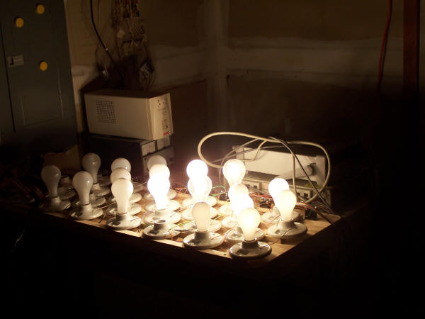
The last time I ran the load test, it was by connecting the "dummy
load" of ordinary incandescent lamps directly to the Prius battery.
The lamps ran on DC. For this test, the lamps are connected to the
output of the UPS, i.e., 230VAC. A slight change to the test setup
involved connecting the laptop computer I used earlier to the test
instruments via ethernet. You can see the National
Instruments "GPIB-ENET" next to the outlet strip on the bottom right.
The thick orange wire is just an AC extension cord; the thin one is the ethernet cable. The test program is very similar to the original one.
I modified it to scan the voltage from the Prius and the UPS so the
operation of both could be analyzed. |
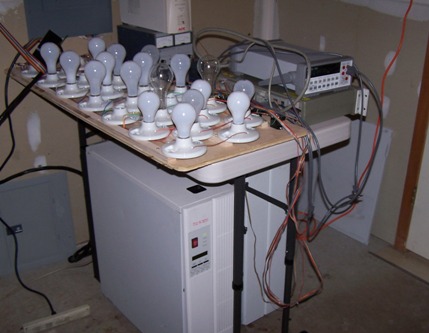 |
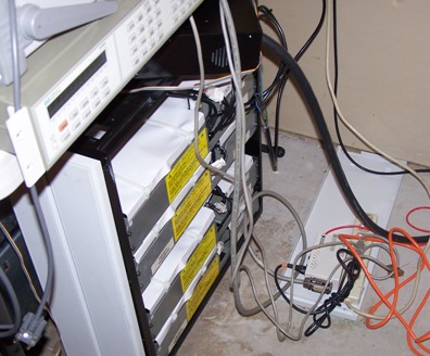
Here's a complete view of the system. The dummy load lamps are
on the left, the switchbox and voltmeter are at the right, the meter box
and a small UPS (for the test equipment only) are behind them.
Under the table repose the UPS and (to its right) the battery cabinet.
The battery cabinet's side is visible in the photo above. The computer running the
test program is in a different room. It gets very hot and very
bright in the test room when the load is powered! |
I ran a number of brief tests at differing power levels (up to about 2400W)
to confirm everything was working correctly and to confirm that the UPS internal
metering was working correctly. I was surprised (and either pleased or
concerned) to see that the UPS only claimed about 10% load at the 2KW level.
Its internal readout has very poor resolution on a character bar graph, so I don't know
whether to make anything of this. The UPS is rated at 12kVA / 8kW.
After confirming that the system was fully functional, I ran a full test by
starting the system on AC, disconnecting AC, allowing the UPS to run the load,
and then connecting the Prius. This test ran for a total of over three hours.
This test scenario is identical to what would be encountered during a 3-hour
power failure, assuming no great amount of electricity was being used in the
house. Initially I would ignore the power failure as the UPS took
over. When it became obvious that power wouldn't be restored promptly, I'd
connect the Prius "extension cord" and turn the car on, at which point it would
supply power. Finally, after a few hours, AC would be restored, I'd turn
off the Prius and disconnect it when reasonably certain that the power emergency
was over.
As with the previous tests, the amount of gas used can't be measured well or
precisely. It would require a much longer test, starting with a full tank,
and a measurement of how much is required to refill the tank, to get a good
reading.
New style of romantic lighting?